

Best Lightning Strike Current Sensors for Accurate Surge Detection
2026-08-22
Lightning doesn’t warn you. One moment your equipment is running fine; the next, a 30,000-amp surge has already found its way in. Accurate surge detection hinges on one often-overlooked component: the current sensor. If it’s too slow, too narrow, or too fragile, the data—and the protection—falls apart. In this article, we’ll break down the best lightning strike current sensors for accurate surge detection, including Xiasen models that consistently deliver fast, precise measurements under real storm conditions.
What Your Current Sensor Misses During a Lightning Strike
A typical current sensor, whether it's a shunt, Rogowski coil, or Hall-effect clamp, is designed for a particular bandwidth. Lightning doesn't care about your bandwidth. The initial return stroke can reach peak current in under a microsecond, which means the signal contains frequency components well into the hundreds of kilohertz or even low megahertz. Most industrial sensors roll off long before that, so the first few microseconds—the part that actually destroys equipment—get smoothed into a gentle curve on your oscilloscope. You see a 20 kA event when the real peak was 80 kA, and the rise time looks like a lazy slope instead of a near-vertical front.
There's also the problem of saturation and residual flux. A current transformer that works fine at 60 Hz can be driven deep into magnetic saturation by the unipolar, high-amplitude lightning waveform. Once the core saturates, the secondary output no longer tracks the primary current. It might even reverse or flatline for a few cycles. Meanwhile, the sensor's own inductance and stray capacitance can ring at their natural frequency, creating phantom oscillations that aren't in the actual current at all. If you're trying to correlate surge arrester operation with actual lightning current, these artifacts can send you down a rabbit hole.
Ground potential rise and common-mode coupling are the sneaky ones. During a nearby strike, the local ground voltage can jump by tens of kilovolts. Your current sensor may be isolated on paper, but that isolation breaks down under the extreme dv/dt. Capacitive coupling across the isolation barrier can inject a false current signal that has nothing to do with the conductor you're measuring. And if the sensor cable runs any distance, the shield current from the ground bounce can induce a differential voltage that looks like a legitimate current reading. So the sensor misses the true waveform shape, adds ringing, and may report current that isn't flowing through the intended path.
Three Sensor Specs That Matter More Than Accuracy Ratings
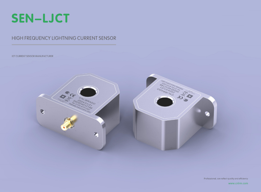
Most engineers fixate on the accuracy number printed on a datasheet, but that single figure rarely tells you how a sensor will behave in your actual process. Take response time: a sensor with excellent static accuracy can be useless if it takes half a second to settle while the measured variable swings wildly. In any loop or fast-changing environment, a sluggish sensor turns precise readings into stale data, and the control system ends up chasing ghosts. A 0.1% accuracy spec won't save you when the reading arrives 300 milliseconds too late.
Repeatability often matters more than absolute accuracy because most systems get calibrated against a known reference anyway. What you can't easily calibrate away is drift or run-to-run variation. A sensor that returns 9.98, 10.02, and 9.99 for the same 10.00 input is far more useful than one that reads 9.85, 10.15, 10.05 even if the second sensor's average is closer to perfect. Processes built on trend detection, sorting, or closed-loop adjustments rely on consistent, predictable readings rather than rare pinpoint hits.
Resolution is the third spec that silently determines how well a sensor works in practice. A device with moderate accuracy but fine resolution can still detect small relative changes, which is often all you need for monitoring drift or catching subtle process shifts. If a temperature sensor reports in whole degrees, a 0.5°C deviation might disappear between readings; a sensor with 0.01°C resolution exposes that shift instantly. Absolute accuracy tells you where you are, but resolution tells you which way you're moving.
Rogowski Coil or Hall Effect? A Field Test Breakdown
I've spent enough time in substations and motor control centers to know that the choice between a Rogowski coil and a Hall effect sensor is rarely settled on paper. The real answer shows up when you're standing next to a live bus, holding a clamp meter, and watching the waveform dance on a scope. Rogowski coils don't saturate, which is a lifesaver when you're measuring a 10,000-amp fault current that would turn a Hall sensor into a paperweight. But then again, Hall sensors give you a DC offset reading without any integrator drift—try getting that from an air-core loop on a cold morning.
In one side-by-side test on a variable frequency drive output, the Hall probe tracked the low-frequency fundamental cleanly but picked up switching noise that made the reading jump around. The Rogowski, wrapped around the same conductor, smoothed out that high-frequency hash yet struggled to hold a steady zero when the load went light. We ended up using the Hall for the DC bus work and the Rogowski for the AC line side, because each one has a blind spot the other doesn't.
So the breakdown isn't about which sensor is better in a lab. It's about what you're actually measuring at 2 a.m. with gloves on and a deadline. If you need wide bandwidth and can't risk saturation, grab the Rogowski. If you need true DC response and don't mind a little nonlinearity near the rails, the Hall effect will get you home. Neither one wins every fight.
Why Saturation Ruins Surge Data Before You Even See It
Saturation doesn't distort surge data—it amputates it. When a sensor or input channel hits its upper limit, every peak above that threshold gets flattened to the same ceiling value. The result is a dataset that looks clean on the surface but has already lost the very information it was meant to capture: the true magnitude and shape of the surge. By the time this data reaches your dashboard, the tallest spikes are indistinguishable from moderate ones, and any analysis based on raw values is working with a lie of omission.
The damage often goes unnoticed because saturation preserves order. Smaller surges still appear smaller; larger ones just don't appear larger. That selective blindness is dangerous in operational settings. A system monitoring power draw, network traffic, or footfall can show a perfectly smooth trend while a catastrophic overload builds silently underneath. Alerts keyed to absolute thresholds may never fire, and machine learning models trained on saturated histories learn to see ceilings as normal behavior. The data doesn't look broken—it looks calm, which is exactly why it's broken.
Preventing this requires treating saturation as a design flaw, not a data quality issue to fix later. You need to know the sensor's range, the analog-to-digital converter's headroom, and the expected surge envelope before deployment. Where saturation is possible, use logarithmic sensing, automatic gain switching, or redundant channels with different scales. Otherwise, you'll keep making decisions from data that has already been silently cut down to size before you ever see it.
Reading the Waveform: Telltale Signs of a Trustworthy Sensor
A good sensor waveform doesn’t need to be flawless, but it does need to be repeatable. Fire the stimulus a few times and keep your eye on the rising edge. If it lands at the same voltage every sweep, with only a whisper of jitter, that’s usually a healthy output stage. A ragged, wandering edge is often the first leak of a failing driver or a loose ground reference.
Next, look at the flat parts. A trustworthy sensor will settle into a quiet baseline with only a thin band of inherent noise. If the trace shows slow wandering, popcorn jumps, or bursts of fuzz that appear and disappear, stop trusting the numbers. That isn’t signal; it’s the sensor arguing with its own front end.
Ringing after a transition is fine only when it decays quickly and stays consistent from sweep to sweep. A couple of damped cycles are normal. If the overshoot grows with temperature, or the ringing gets sharper on some channels, suspect a cracked bond wire or marginal decoupling. Confidence comes from a waveform that stays boring under repeated tests.
Can a Budget Sensor Keep Up with Fast Transients?
Budget sensors often struggle when faced with sharp voltage spikes or rapid current changes. Their limited bandwidth and slower sampling rates mean that short-lived transients can slip through unnoticed, leaving engineers with a distorted picture of what actually happened. In practice, you might see a rising edge that looks rounded off, or a ringing that never gets captured, simply because the sensing element and the front-end electronics cannot react quickly enough.
That said, not every fast transient demands a top-tier instrument. If the signal of interest is dominated by lower-frequency components, or if you only need a rough indication of peak amplitude rather than exact timing, a budget sensor can still earn its keep. The real question is whether the missing high-speed detail matters for your specific test. For power supply ripple checks or basic fault detection, a cheaper sensor might be perfectly adequate; for switch-node ringing or ESD events, it will likely leave you guessing.
Some lower-cost sensors compensate with clever filtering or oversampling tricks, but these can introduce their own artifacts. You may get a smoother waveform, yet lose the true shape of the transient. In the end, matching the sensor's response time to the fastest edge you expect is the only reliable way to avoid false confidence. A budget sensor can keep up with fast transients only when those transients are not truly fast by the sensor's own standards.
FAQ
Lightning strokes rise in microseconds and carry tens of kiloamps, so the sensor needs wide bandwidth (at least tens of kHz to MHz), galvanic isolation, and a non-saturating core or coreless design. Standard CTs with iron cores often saturate and distort the fast edge, while Rogowski coils or fiber-optic current sensors preserve the waveform.
A shunt introduces a direct metallic path and can't easily handle the full lightning energy without large physical size and thermal management. Rogowski coils are inherently isolated, lightweight, and don't saturate; the integrator reconstructs the current from the coil's di/dt output, allowing accurate capture of high-frequency components without breaking the conductor.
Continuing current lasts milliseconds and carries significant charge, but a sensor with high-pass behavior above a few hundred Hz will miss it. For accurate surge detection, choose a sensor with a low-frequency response down to 0.1 Hz or DC if possible, otherwise the measured waveform will drop the slow tail and underestimate total charge.
Placing the sensor near bends, parallel conductors, or magnetic steel can distort the field and introduce crosstalk. The sensing loop should be centered on the conductor, secured away from return current paths, and shielded if possible. A common error is routing the signal cable next to the down conductor, which induces common-mode noise that mimics a strike.
Open-loop Hall sensors typically lack the bandwidth and dynamic range for a full lightning impulse, and closed-loop Hall sensors with enough aperture for large conductors are bulky and expensive. They work better for residual current or slow surge monitoring. For direct strike measurement, a Rogowski coil or a fiber-optic current sensor is usually the practical choice.
Peak current requires accurate amplitude response across the front time, while specific energy depends on the squared waveform over the full duration. A calibration that only verifies a 50 Hz sine wave won't guarantee performance for a 10/350 µs impulse. The sensor should be characterized with surge waveforms covering both fast front and long tail, otherwise the I²t value can be off by more than 20%.
The sensing element is passive and dielectric; it uses the Faraday effect in an optical fiber instead of a conductive coil or semiconductor. The signal is transmitted as light, so it isn't affected by the strong electromagnetic pulse from the strike. This removes the need for heavy shielding and reduces false triggers from induced voltages.
Look for a flat frequency response from a few hertz to at least 100 kHz, a dynamic range covering 100 A to 200 kA without range switching, and a delay-free analog output or high-speed digital link. Also check that the sensor can survive repeated 10/350 µs impulses without demagnetization or thermal drift. Portability and clamp-on design matter more for field research than for permanent installation.
Conclusion
Most lightning current sensors fail not in the lab but in the field, where a strike's rising edge arrives faster than the sensor's internal electronics can track. What your device misses isn't a subtle drift - it's the first few microseconds where the real damage begins. Three specs deserve more attention than headline accuracy - bandwidth, di/dt, and saturation threshold. A sensor rated 0.5% on a steady sine wave can still flatten a 100 kA lightning transient because its core saturates before the waveform peaks. Rogowski coils, with air cores, avoid that magnetic saturation entirely, but they struggle with low-frequency tails and need active integrators that add noise. Hall effect probes offer DC-to-high-frequency coverage but clamp hard when a nearby strike pushes them past their linear range. Field tests on actual strike simulators show the same pattern - the sensor that looks best on a datasheet often loses data in the first half-cycle, exactly when surge protection decisions need clean evidence.
Reading the raw waveform separates honest instruments from the rest. A trustworthy sensor preserves a fast rise without overshoot, shows no flat-topped clipping after the peak, and recovers to baseline without ringing that could be mistaken for restrike. Budget sensors generally miss fast transients because their internal shielding and lead inductance limit the slew rate, not because the amplifier chip is old. If the captured trace shows a smooth, monotonic rise to peak in under 8 microseconds and no artificial plateau, you're seeing the actual surge, not a filtered version of it. The practical choice isn't always the most expensive - a well-designed Rogowski coil with a high-bandwidth integrator beats a mid-range Hall sensor on fast strikes. But for DC-heavy systems or long-duration monitoring, you'll sacrifice some transient speed for Hall's stability. Knowing which compromise you're making - and seeing it in the waveform - is what separates accurate surge detection from after-the-fact guesswork.
Contact Us
Contact Person: Liu Mengyang
Email: [email protected]
Tel/WhatsApp: 8618727589233
Website: https://www.cnlrm.com/en/