

Best Optical Comparator for Precision Measurement and Inspection
2026-09-22
Ask a machinist what the best optical comparator looks like, and they won't describe a spec sheet. They'll describe the moment a questionable edge becomes a clear pass or fail. Precision measurement and inspection live or die by that moment, which is exactly where JATEN focuses its design energy. This guide breaks down what separates a dependable comparator from an expensive paperweight.
Optical Comparator Basics: How They Deliver Repeatable Precision
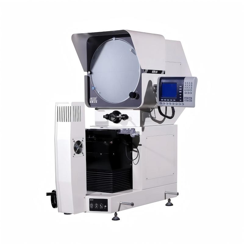
Optical comparators project a magnified silhouette of a part onto a screen, letting you compare its outline against a transparent template or measured dimensions. Because the measurement is non-contact, there is no probe force deforming the workpiece, and the image stays stable from one inspection to the next.
The repeatable precision comes from a few mechanical and optical choices. Fixed magnification lenses eliminate zoom drift, while a rigid cast-iron stage and heavy base damp vibration. A consistent, collimated light source keeps the shadow edge sharp, so an operator sees the same boundary every time without recalibrating between parts.
Routine checks with a known master or calibration grid lock in that consistency. Once the screen scale is verified, you can place a part on the stage, align it against the overlay, and trust that today’s reading will match tomorrow’s—no warm-up drift, no stylus wear, no interpretation differences between operators.
Choosing the Right Lens and Stage for Complex Part Inspection
复杂零件的检测失败往往不是算法问题,而是光学前端选型不当。对于带有深孔、倒角或高反射曲面的零件,标准定焦镜头产生的透视误差会让边缘位置漂移几个像素。此时远心镜头比单纯提高分辨率更有效,它能在一定景深内保持恒定放大倍率,确保不同高度的特征测量值一致。同时要计算最小可分辨特征对应的数值孔径,而不是盲目追求大靶面相机。工作距离受限于夹具和照明空间时,折反射或紧凑型远心设计可以避免机械干涉。
载物台的精度直接决定重复检测的散差。三轴直线平台如果只标注单向重复定位精度,实际往返检测时回程间隙会引入两倍以上的误差。选择带预紧的滚珠丝杠或直线电机,并配置直线光栅尺做闭环反馈,才能让复杂零件的多面检测保持坐标一致性。对于需要倾斜观察侧壁或底部倒扣的零件,五轴台或至少一个高刚性旋转轴比软件拼接更可靠。负载能力也要留出至少30%余量,因为夹具和旋转中心的偏载会放大俯仰误差。
镜头和载物台最终要作为一套系统来评估,而不是孤立参数。把镜头装在振动隔离的光学平台上,但载物台驱动时产生的低频振动仍可能传递到成像光路。使用短而粗的立柱、将运动轴与成像轴解耦,并在载物台基座下加阻尼垫,通常比单纯提高曝光速度更能改善图像清晰度。另外,热漂移对长周期检测的影响常被低估:电机和照明热源会让镜头法兰距和载物台原点在半小时后偏移几个微米。在关键工位设置温度传感器并做开机预热标定,比频繁手动归零更实际。
Lighting and Contrast Techniques for Hard-to-See Features
Sometimes the smallest defects only show themselves when light hits the surface at a shallow angle. Raking light from a low-positioned flashlight can turn invisible scratches, dents, and texture variations into dramatic shadows that are easy to spot. Move the light around slowly rather than keeping it fixed; this changing angle reveals features that disappear under direct overhead lighting.
Contrast can be pushed further by pairing the right background with a simple polarizing filter. A dark, non-reflective surface behind a translucent or glossy subject often makes edge irregularities stand out. If your subject is metallic or highly reflective, try cross-polarization: place a polarizing film over the light source and another over the lens, then rotate one until glare drops away and the underlying pattern emerges.
For very faint color differences, such as hairline cracks or worn markings, a low-contrast scene can be lifted with a narrow-band light source or a colored gel. Blue or green light tends to increase the perceived separation between a pale feature and its background, while a slightly underexposed image can keep highlights from washing out the detail you are trying to see.
From Setup to Measurement: Workflow Tips That Reduce Operator Error
Operator error rarely starts at the measurement step. It usually creeps in during setup, when instruments are left in default modes, cables are connected in a hurry, or the test sequence doesn't match the way a person actually works. A more reliable workflow begins by turning setup into a short checklist that is tied to the physical layout of the bench, not to a generic manual. For instance, placing a small laminated card next to the signal generator that says “confirm termination before powering on” does more than any lengthy procedure document.
Once the setup is predictable, the handoff to measurement becomes the next failure point. Instead of relying on memory, build the measurement routine so that each reading is taken in the same order and under the same conditions. If possible, add a quick midpoint sanity check—something like comparing a known reference value before collecting the real data. This catches drift, loose connections, or a wrong range setting before they turn into bad results. Small physical reminders, like colored tape on the dial position or a marked cable path, often reduce mistakes more effectively than extra training sessions.
Finally, treat the last step—recording the measurement—as part of the workflow rather than an afterthought. Have the operator write down the value immediately, using a fixed format that includes units and test conditions. If the data goes into software, use a template with locked fields so nothing is skipped. The goal is to make the correct action the easiest action, so that reducing operator error doesn't depend on constant attention but on a setup-to-measurement flow that quietly guides the hands.
Maintaining Calibration Accuracy in High-Volume Production Environments
Calibration in high-volume settings rarely fails as a single dramatic event. It erodes gradually through thermal cycling, vibration, and the slow accumulation of particulate contamination on sensor windows. Operators who rely on periodic checks alone often miss the subtle drift that occurs between scheduled maintenance windows, especially on lines running three shifts. The most reliable defense is to embed reference verification into the normal production cadence—measuring a certified artifact at fixed intervals and comparing the result against an expected band that tightens as historical variability becomes better understood.
A practical approach is to treat calibration data as a live process variable rather than a compliance checkbox. Short-term variation from multiple measurements on the same reference part can reveal whether drift is coming from the instrument, the fixturing, or the environment. For instance, if repeat measurements of a master gauge show increasing spread without a mean shift, it often points to looseness in the clamping mechanism or air pressure instability—not a fundamental sensor problem. Catching these patterns early prevents the usual firefighting where entire batches are quarantined after an out-of-tolerance discovery.
Finally, shift-to-shift consistency matters as much as absolute accuracy. A machine that passes a morning verification but drifts after lunch due to ambient temperature swings may still ship product that is technically in spec but unnecessarily close to the tolerance edge. Linking calibration checks to specific environmental triggers—like a 2°C change on the shop floor or a sudden drop in line speed—gives technicians a more actionable signal than fixed calendar intervals alone. This keeps the focus on preventing the conditions that cause drift, not just correcting for it after the fact.
Comparing Optical Metrology to CMM and Vision Systems for Tight Tolerances
Choosing the right measurement tool for tight-tolerance parts rarely comes down to a simple accuracy spec. CMMs remain the reference for many dimensional checks because their tactile probes deliver repeatable point-by-point data on prismatic features like bores, slots, and datum planes. However, that same contact approach can slow down inspection of contoured surfaces and may deflect thin or flexible components, which becomes a real problem when tolerances are only a few microns.
Optical metrology systems avoid those contact forces by projecting structured light or capturing laser scans across the entire surface at once. The resulting point cloud offers far denser coverage than a discrete CMM probing routine, making it easier to spot form deviations that a handful of touch points would miss. Vision systems, by contrast, excel at fast edge detection and two-dimensional feature presence, but their depth resolution and ability to hold micron-level 3D tolerances often fall short on complex geometry.
In practice, the comparison is not about declaring one technology universally better. Shiny or clear surfaces can challenge optical sensors and require a matte coating, while deep internal bores and hidden undercuts may still demand a tactile probe. Vision inspection can run quickly near the line but usually needs stable lighting and well-defined edges. The best approach for tight tolerances is often a mix: CMM for critical datums and calibration, optical scanning for full-surface form and reverse engineering, and vision only where 2D feature location is the dominant requirement.
FAQ
It handles rapid checks without touching delicate surfaces, so you get repeatable readings even when parts are oily or have fine features that contact tools might distort.
Screen size should match the largest dimension you typically inspect plus a little breathing room for profile tracing. A 14-inch screen works for small turned parts, while larger stamped or molded components often benefit from a 30-inch or bigger display.
It's primarily for 2D profile and contour comparison, so it's not a surface roughness tool. You'll see scratches and gross texture, but for Ra or Rz values you still need a profilometer.
Skipping stage calibration after moving the machine, using worn overlay charts, and not aligning the light path square to the part. Those small errors quietly add up to bad pass/fail calls.
A digital model replaces the glass screen and overlay charts with a camera and software, making it easier to store measurements, apply geometric tolerances, and automate edge detection rather than relying on an operator's eye.
Yes, when you set up a dedicated fixture and a clear overlay for one part number, operators can check features in seconds. It's slower than a full vision system for complex multi-axis parts but much faster than manual hand tools for repetitive profiles.
Profile lighting gives a sharp silhouette for outside edges and through-holes, while surface lighting helps with blind pockets, engraved marks, or recessed areas that disappear under backlighting.
Use a certified glass scale or a known master part at the start of each shift, and check both X and Y axes plus magnification. If readings drift beyond your tolerance band, recalibrate the stage and check for loose mounts.
Conclusion
Finding the best optical comparator for precision measurement and inspection often hinges on how reliably the machine turns small details into repeatable numbers. A solid comparator pairs a stable telecentric lens with a stage that moves smoothly without play, letting you check complex profiles without constantly re-zeroing. Hard-to-see features, like faint edge breaks or surface transitions, respond well to adjustable surface and profile lighting, and some shops add green or monochrome filters to cut glare on polished parts. Once setup becomes intuitive, operators tend to make fewer mistakes; simple fixtures, digital readouts, and saved part programs go a long way toward keeping measurements consistent from one shift to the next.
In high-volume production, accuracy is only as good as your calibration routine. Frequent checks with a certified glass scale or master artifact prevent drift, and temperature-stable components reduce thermal error without constant re-compensation. When tolerances tighten, an optical comparator may not always match a CMM for 3D geometry or a vision system for sub-micron edge detection, but its direct optical path and large field of view make it surprisingly competitive for turned parts, threads, and stamped profiles. Choosing the right comparator means balancing these factors: rigidity, lighting flexibility, and a workflow that doesn't ask too much from the person standing at the screen.
Contact Us
Contact Person: Volien
Email: [email protected]
Tel/WhatsApp: +86 18029161762
Website: https://www.jatentech.com/