

China Steel Pipe Tower Solutions for Reliable Power Transmission Infrastructure
2026-10-16
Every reliable power grid depends on more than just cables—it stands on towers engineered to endure. Anbang brings China steel pipe tower solutions to the forefront of transmission infrastructure, combining precision manufacturing with field-proven resilience. Ready to see what makes these towers the quiet backbone of modern energy?
Designing Pipe Towers for 50-Year Service in Humid Subtropical Climates
A 50-year service life in a humid subtropical setting starts with the right metallurgy. Standard ASTM A572 or A36 structural steel will not survive without a robust allowance, but adding 3 mm of sacrificial thickness to every member often introduces unnecessary weight. A better approach pairs modest corrosion allowances on primary tubes with selective use of stainless steel for pins, splice bolts, and base plate hardware, where galvanic couples and thin cross-sections concentrate damage. For towers within 5 km of the coast, consider 316L stainless for the lower 3 metres and specify hot-dip galvanizing to ASTM A123 with a minimum 85 µm zinc thickness elsewhere, followed by an epoxy intermediate coat and a urethane topcoat.
Moisture management governs detail design. Humid subtropical climates alternate between heavy rain, high dew points, and intense sun, so trapped water becomes a long-term corrosion driver. Every closed pipe section should be either fully seal-welded and internally coated, or fitted with 10 mm weep holes at the lowest point and vent holes near the top to allow airflow. Avoid overlapping plates that form capillary crevices; where unavoidable, seal the edges with a flexible polyurethane caulk after galvanizing. Anchor bolt pockets need a sloped grout surface and a drain path to prevent standing water against the base plate weld.
The 50-year requirement also shapes access and maintenance planning. Coating systems in this climate rarely last more than 15–20 years, so the tower should include permanent ladders, rest platforms, and attachment points for rope access without welding. Design the flanges and splice joints so any recoating crew can reach all surfaces with a brush or spray gun; hidden areas behind gussets and inside tight angles should be closed off or given an easily removable cover. Specify batch numbers and coating DFT readings at handover, and include a simple inspection schedule tied to seasonal dry periods rather than arbitrary calendar intervals.
How Weld Seam Placement Affects Fatigue Life Under Wind Loads
Fatigue failures in welded structures under fluctuating wind loads rarely begin in the base metal itself. Instead, they almost always initiate at the weld toe or root, where microscopic discontinuities and residual stresses concentrate the cyclic strain. When a weld seam is positioned in a region that experiences high tensile stress range during each gust cycle, the local stress concentration can exceed the endurance limit of the material even if the nominal stress appears moderate. Moving the seam away from such hot spots—for instance, shifting a circumferential weld away from a stiffener or a section change—can reduce the peak stress intensity by an order of magnitude.
Placement relative to the neutral axis also matters. A fillet weld running along a flange where bending-induced tensile stresses peak will accumulate fatigue damage far faster than the same weld placed along the web near the neutral axis, where stress range is minimal. In tubular towers or monopole bases, relocating a longitudinal seam from the windward side (where tension alternates with compression) to a side that sees primarily compressive or lower-magnitude cyclic stress can extend the predicted fatigue life by several times. The improvement is not linear; because fatigue crack growth follows a power law relationship with stress range, a 30% reduction in local stress can yield a threefold or greater increase in cycles to failure.
One common mistake is treating weld placement as a secondary detail after structural sizing is complete. By then, the member thickness and geometry are fixed, and the only option is to grind or peen the weld to improve its profile. Designing the joint layout so that welds sit in low-stress zones from the start is far more effective. For example, in a lattice tower connection, placing the weld on the compression side of a gusset rather than the tension side can push the critical crack initiation site into the base metal, where fatigue strength is substantially higher. Wind loads are inherently variable, so any weld that experiences a wide stress range over millions of cycles will eventually fail; the goal of placement is to make that failure occur long after the structure’s intended service life.
Why Chinese Suppliers Now Use Laser Cutting for Slip Joints
The shift toward laser cutting for slip joints didn't happen overnight. For years, Chinese factories relied on stamping, plasma cutting, or even manual grinding to shape the interlocking parts. Those methods work, but they leave burrs, create heat distortion, and demand extra finishing steps. A slip joint needs to slide smoothly without binding, and even a small burr can ruin the fit. Laser cutting eliminates that problem almost entirely. The beam doesn't touch the metal, so there's no tool wear and almost no thermal stress. Edges come out clean enough to use as-is, which cuts out a whole secondary operation.
Precision is another reason this technology caught on so quickly. Slip joints rely on tight tolerances between the inner and outer sleeves. If the gap varies by more than a fraction of a millimeter, the joint either leaks or seizes up. Traditional cutting methods have a natural variability, especially as cutting dies wear down or operators adjust machines by hand. Laser cutting, once the program is set, repeats the exact same cut on every single part. Batch after batch, the dimensions stay consistent. That consistency means fewer rejected assemblies and fewer customer complaints down the line.
Cost and speed also play a big role. A modern fiber laser can run unattended for hours, loading sheets automatically and cutting complex profiles faster than any mechanical process. Material waste drops because the laser can nest parts tightly together, leaving only a thin skeleton behind. Labor costs fall since one operator can supervise multiple machines. For Chinese suppliers working on tight margins and short lead times, that combination of lower scrap, fewer finishing steps, and round-the-clock operation simply makes more sense than sticking with older methods. It's not just about keeping up with technology; it's about staying profitable when customers demand both quality and speed.
Zinc Coating Thickness: The Often-Ignored Factor in Ground Corrosion
When underground steel corrodes, the blame usually falls on aggressive soil chemistry, poor drainage, or inadequate cathodic protection. Zinc coating thickness rarely enters the conversation, even though it sets the hard limit on how long the sacrificial layer can keep doing its job. In buried conditions, the coating is consumed unevenly, and a few extra microns can mean the difference between a structure that lasts decades and one that needs excavation and repair far sooner than expected.
Thicker zinc alone is not a guarantee, but it changes the risk profile in ways that matter on site. Soils with low resistivity, high chloride content, or significant moisture will eat through zinc faster, and backfill damage during installation can remove part of the coating before service even begins. At the same time, going too thick has downsides: heavier coatings may be more prone to cracking under mechanical stress or thermal cycling, and the added cost may not always be justified if the surrounding soil is relatively benign. The key is to match coating thickness to the actual burial environment rather than defaulting to atmospheric corrosion guidelines.
A practical approach is to treat zinc thickness as a design variable tied to soil aggressiveness and expected service life. For buried steel, field measurements and failure histories often show that coating thickness requirements need to be more conservative than what typical product datasheets suggest. Specifying a minimum measured thickness, verifying it after galvanizing, and accounting for local wear during transport and backfill can close the gap between laboratory assumptions and ground-level reality. Until that becomes standard practice, zinc coating thickness will keep operating as a silent factor in ground corrosion.
Reducing Erection Time with Preassembled Crossarm Connections
Preassembled crossarm connections strip hours out of field erection by moving complex bolting and alignment work into controlled shop conditions. Instead of wrestling with loose hardware at height, crews lift a single, ready-to-bolt assembly into place and drive a handful of fasteners. This shift cuts crane time, reduces the number of workers exposed on the structure, and keeps the critical path moving even when weather or terrain would normally slow traditional stick-by-stick assembly.
The real gain comes from eliminating the small, repetitive tasks that eat schedule without showing up clearly on paper. Torquing multiple brace connections, squaring the crossarm, and rechecking bolt tension are absorbed into the preassembly process, where jigs and fixtures make repeatability fast. Field crews then focus on positioning and final tightening rather than sorting parts or correcting misalignment after the fact.
For projects with repetitive tangent structures, the time saved per erection compounds quickly. A crew that can set three preassembled crossarms in the time it once took to build one from loose members changes the entire outage or construction window. The approach also lowers the chance of lost hardware and dropped tools, which are common hidden delays on lattice towers and H-frame lines.
Case in Point: A 220 kV Line Across Flood-Prone Wetlands
When a 220 kV transmission line was proposed to connect two growing load centers, the most direct route sliced through a sprawling wetland that floods every rainy season. The corridor was not just wet—it was dynamic, with water levels rising two to three meters within days and soils that turned to soup underfoot. Early surveys showed conventional lattice towers would need massive, costly foundations and still risk being undermined by scour.
Engineers shifted the alignment to follow slightly higher ground along an old levee, then designed towers with grouped pile foundations driven deep into stable clay below the muck. Each tower was raised an extra four meters, keeping conductors well above the highest recorded flood level. Construction happened only during the dry months, and materials were staged on temporary mats to avoid churning the wetlands. Helicopters set the upper tower sections and stringed the conductors, eliminating the need for access roads through sensitive areas.
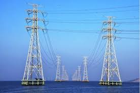
The line now sits quietly above the seasonal floods, with towers that appear to float on the water during the wettest months. Monitoring after three flood cycles shows no significant erosion or foundation movement, and the wetland continues to function as before. It is a reminder that linear infrastructure and flood-prone ecosystems can coexist when the design starts from the landscape rather than fighting it.
FAQ
Typical configurations include suspension towers for straight runs, angle and tension towers for direction changes or anchoring, terminal towers at substation entries, and special crossing towers for rivers or highways. Chinese fabricators regularly produce units rated from 110 kV up to 1000 kV and beyond, with designs adjusted to the specific conductor bundle and span requirements.
Because a pipe structure has a much smaller base footprint than a lattice tower, it can be placed in narrow corridors, along roadways, or in agricultural land without consuming excessive space. The smooth, tapered profile also blends better in urban or scenic areas, and some suppliers offer painted or camouflaged finishes to reduce visual impact.
Hot-dip galvanizing is the standard, usually applied after all welding and drilling, to create a uniform zinc layer over the entire surface. In highly corrosive coastal or industrial environments, additional coatings such as epoxy or polyurethane topcoats can be specified. Quality checks include coating thickness measurements and adhesion tests to confirm the barrier will last for decades.
Yes. Manufacturers typically perform structural analysis using software like PLS-CADD or similar, based on project-specific wind speeds, ice thickness, temperature ranges, and ground acceleration data. This allows the tower body, flanges, and base plate to be sized correctly, whether the project is in a typhoon-prone region, a high-altitude icing zone, or an earthquake-active area.
Reputable Chinese fabricators provide material mill certificates for each steel batch, welding procedure specifications, qualified welder records, dimensional inspection reports, galvanizing thickness logs, and pre-assembly photographs or videos. Many also support third-party inspections by agencies like SGS, BV, or the buyer's own technical team.
The towers are normally fabricated in sections with flanged connections, allowing them to be bundled and shipped either in open-top containers, flat racks, or break-bulk vessels depending on section length and weight. Packaging plans are tailored to port handling capabilities and road limits at the destination, with markings and shipping lists to ease site inventory.
The essential information includes nominal system voltage, conductor and ground wire type, basic span and angle details, wind and ice loading assumptions, soil or foundation data if known, tower quantity and type list, and the reference standard to follow such as IEC 60826, ASCE 10, or a national code. Clear right-of-way constraints or height restrictions should also be flagged early.
Yes, many Chinese manufacturers can supply tapered monopoles, polygonal steel tube poles, camouflaged or decorative poles for urban substation feeders, and even hybrid structures for telecommunication attachments. These can be produced with custom color coatings, concealed cable entry, and reduced visual profiles while maintaining full structural capacity.
Conclusion
In humid subtropical regions, ordinary transmission towers rarely survive two decades without heavy maintenance, so the shift toward pipe towers built for a 50-year service life is notable. Chinese manufacturers have focused on two details that make a real difference: weld seam positioning and laser-cut slip joints. Moving welds away from high-stress zones under cyclic wind loads reduces the risk of fatigue cracks that often start at the seam. Laser cutting, now standard in many Chinese shops, gives slip joints a tighter fit, which means less bolt loosening and better load transfer. On top of that, buyers are paying closer attention to zinc coating thickness at the buried section, where soil moisture and salts eat through thin galvanizing faster than anyone expects.
Field assembly is another area where time equals money. Preassembled crossarm connections let erection crews lift larger sections into place with fewer crane picks and less bolting at height. A recent 220 kV line across flood-prone wetlands showed how these choices add up. The towers were designed with extra corrosion allowance below ground, laser-cut slip joints for quick alignment, and preassembled crossarms that cut on-site labor by nearly a third. Even after seasonal flooding and prolonged high humidity, the line has stayed in service without the usual coating failures or joint loosening. That kind of performance explains why Chinese steel pipe towers are gaining trust in markets that demand long-term reliability rather than just lower upfront cost.
Contact Us
Contact Person: antor khan
Email: [email protected]
Tel/WhatsApp: 8613863903569
Website: https://www.qdabtower.com/