

Top 10 Three-Phase Current Transformers for Accurate Power Measurement
2026-08-31
Getting accurate three-phase power readings isn't just about the meter—it's the current transformer that often makes or breaks the measurement. That's why we've sorted through the noise to bring you ten three-phase current transformers worth your attention, from proven industrial workhorses to precision-focused options like Xiasen. If you're tired of guessing which CT will hold its accuracy under real load conditions, this list gives you a practical starting point.
Why a 0.2s Accuracy Class Usually Isn't Optional for Revenue Metering
Revenue metering isn't about approximate readings; it's the financial ledger between a utility and a paying customer. When energy flows are large, even a fraction of a percent error becomes a six-figure discrepancy over a billing cycle. The 0.2s class narrows that margin enough to make disputes rare, and for high-voltage interconnections or industrial users, regulators simply won't accept less.
The "s" in 0.2s matters more than many realize—it holds accuracy down to low current levels where older meters drift. A facility that idles overnight or a solar farm exporting partial output still needs exact metering, not just at full load. That's why most merchant power contracts specify 0.2s as a floor, not a luxury; the cost of a lower-class meter is trivial next to the potential billing corrections.
Once you factor in transformer losses, temperature swings, and CT/PT errors, a 0.5s meter can eat into operating margins without anyone noticing until a third-party audit. Choosing 0.2s from day one avoids retrofits, legal friction, and the awkward conversation about why last year's invoices were systematically off.
How Burden Impedance Steals Precision from Your Three-Phase CT
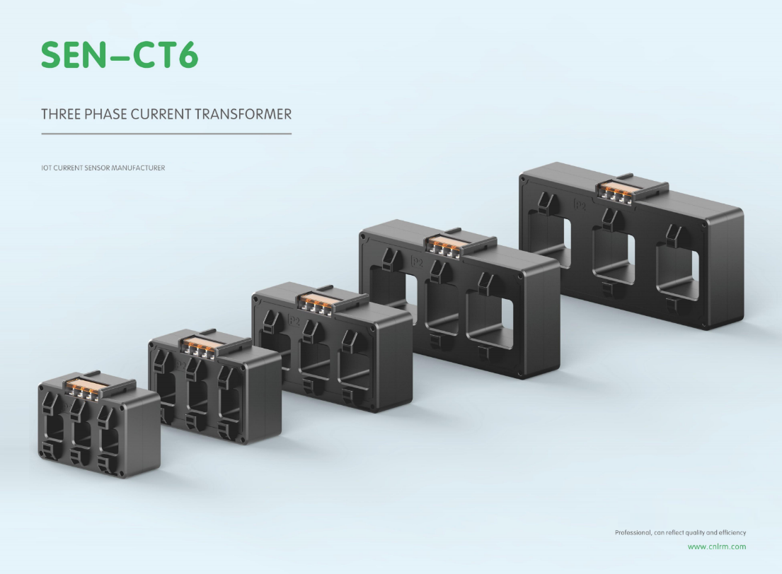
Every lead, terminal, and relay input wired into a three-phase current transformer adds a little opposition to the secondary current. That collective load is the burden, and it quietly defines how faithfully the CT can reproduce primary current. As burden impedance climbs, the CT must drive more voltage to push the same secondary current through the loop. Beyond a certain point the core can no longer keep up, and the magnetizing branch starts stealing current that should have gone to the protection or metering equipment. The result is a secondary waveform that looks smaller than it should and drifts further from the ideal phase relationship.
In three-phase installations the problem rarely stays symmetrical. One phase may have a longer cable run, a slightly different relay input, or an older connection with higher contact resistance. That phase then operates closer to its saturation knee under normal load or during faults, producing a ratio error the other two phases don't share. A differential or overcurrent scheme that assumes balanced secondary currents will see this as a real unbalance, and the protection may either trip when it shouldn't or sit idle when it should. Even metering accuracy suffers: a few extra tenths of an ohm in the burden can push energy readings outside the class accuracy limits, especially at lower primary currents where the CT has less margin to give away.
Split-Core vs. Solid-Core: Choosing Without Relying on Vendor Hype
The split-core versus solid-core debate usually starts with spec sheets, but that's exactly where vendor hype creeps in. The real deciding factor is the installation context. If you're building a new panel and can pass conductors through before termination, a solid-core CT is often the more straightforward choice—fewer failure points, slightly better long-term stability, and typically lower cost. But if you're retrofitting an existing system where disconnecting cables means expensive downtime or safety risks, the split-core design stops being a luxury and becomes the only practical option, regardless of what a marketing brochure says.
One persistent myth is that split-core CTs are always less accurate. That might have been true twenty years ago, but modern split-core models frequently match solid-core accuracy across the 5% to 120% rated current range. The catch is that accuracy depends more on your actual load profile than on the headline class rating. A solid-core unit rated for high accuracy at full load can perform poorly at low currents, while a well-designed split-core may hold its own under partial loads. The real question is how the device behaves at the currents you actually measure—not what the spec sheet highlights in bold.
Price comparisons also hide more than they reveal. A solid-core CT is usually cheaper as a component, but if installing it requires a shutdown, temporary bypass, or reworking busbars, those costs can dwarf the savings. Split-core units carry a higher upfront price, but that premium often vanishes the first time you avoid taking a production line offline. At the same time, don't let sellers convince you that "convenient opening" means zero maintenance. Split-core joints can degrade in humid or vibrating environments, so ask whether the unit will still hold its accuracy after five years. A few conversations with technicians who have installed both types in similar conditions will teach you more than any glossy comparison chart.
Field Verification Tricks for CT Ratio and Polarity in Live Panels
One quick sanity check for CT ratio on an energized panel is to clamp a true RMS meter around the secondary lead and compare it against the expected primary current divided by the nameplate ratio. If the panel is pulling 80 A on the primary and you have a 200:5 CT, you should see roughly 2 A on the secondary. Anything wildly off usually points to a shorted turn, wrong tap, or a CT that was never wired to the meter.
Polarity checks in a live panel often come down to watching the phase angle between voltage and current on a power quality analyzer. With P1 facing the source and P2 toward the load, the current should lag the voltage by the load's power factor. If you see a 180-degree flip, reverse the secondary leads or swap the polarity marks. A simpler trick is to use a battery and an analog voltmeter on de-energized CTs, but in a live panel a phase-angle reading is usually the fastest confirmation.
When multiple CTs share a neutral or common return, isolate one secondary at a time if possible, otherwise leakage currents can make your ratio reading look off by 10–20%. Also, never open-circuit a live CT secondary; use a shorting block or test switch before unplugging meter leads.
When Phase Angle Error Matters More Than Ratio Error
Most discussions of current transformer accuracy start with ratio error, but phase angle error quietly becomes the dominant source of measurement uncertainty in low-power-factor applications. Consider a revenue meter connected to an industrial load with a power factor of 0.5. A CT with a modest phase displacement of 30 minutes—only half a degree—shifts the measured current angle relative to the voltage. The resulting error in real power is proportional to the tangent of the load angle, so at a 60-degree phase angle that half-degree error produces roughly a 1.5 percent error in the watt-hour reading. A ratio error of 0.3 percent would be considered unacceptable in the same circuit, yet the phase angle error slips through unnoticed unless the load's power factor is taken into account.
Protective relaying adds another layer where phase angle error outweighs ratio error. Directional overcurrent and distance elements decide whether a fault lies inside or outside a zone by comparing the phase relationship between voltage and current. A small angular shift from a current transformer can tilt the operating characteristic just enough to cause false tripping on a heavy through-fault or delayed operation on an internal fault. Differential schemes for transformers and busbars are even more sensitive: differences in phase angle error between the CT sets on each side generate a spurious differential current that grows with through-current. Even if every CT meets its ratio accuracy class, the cumulative phase mismatch can reach unacceptable levels during external faults.
The same principle explains why phase angle error is ignored in many ordinary measurements. At unity power factor, a half-degree phase error changes the power reading by only a tiny fraction of a percent, so ratio error understandably gets the attention. But the moment the load becomes reactive, or the protection scheme depends on angular relationships, the tables turn. Specifying a current transformer with tight phase displacement limits—not just a good ratio error class—becomes the practical way to keep metering and protection within design margins.
Mounting and Wiring Habits That Keep Accuracy Stable Over Years
Most drift issues don't come from aging sensors or tired components—they come from how the system was put together in the first place. A slight twist in a cable, a connector that was never fully seated, or a mounting screw that gradually loosens with thermal cycling will quietly erode precision long before anyone notices a hard failure. The habit that pays off year after year is to treat every physical connection as part of the measurement loop. That means routing signal wires away from power lines, using strain reliefs so that vibration doesn't work connectors loose, and tightening fasteners to spec rather than by feel.
Another habit that keeps readings trustworthy is to deliberately stress the install before trusting it. After any change—new cable, different mounting plate, even just moving a nearby heat source—run a quick stability check. Log a baseline for a few minutes, flex the wiring by hand, tap the enclosure, and watch for any step change in output. If the signal jumps or drifts, fix the mechanical issue now instead of waiting for it to reappear as a mysterious offset six months later. Over time, this practice builds up a mental map of which mounting positions and cable paths are genuinely stable in your environment, and which only look fine on a bench.
Finally, don't underestimate the slow creep of oxidation and debris. Gold-plated contacts resist corrosion better than tin, but they still need occasional reseating to break through micro-films. Use sealed connectors where moisture is present, and add a small drip loop so condensation runs away from the mating face instead of pooling around it. If you must use screw terminals, mark the torque value on the enclosure and check it once a year. It's tedious, but that annual pass with a calibrated driver is often the difference between a system that holds its accuracy for a decade and one that quietly drifts 0.2% every spring.
FAQ
Focus on accuracy class like 0.5 or 0.2 for revenue-grade work, the burden rating, and whether the CT saturates too early under your expected load. Also check the window size for conductor fit and decide if you need split-core for retrofit jobs.
The class sets the maximum error at rated current. A 0.5 class CT introduces up to 0.5% error, while a 0.2 class cuts that to 0.2%. Over months of metering, that difference compounds, especially on higher loads.
Yes, if you use split-core CTs. They clamp around the conductor without breaking the circuit. Solid-core types need a shutdown and cable disconnect, which is often not practical in live facilities.
The secondary tries to build extremely high voltage, which can damage insulation and create a serious shock hazard. Always short the secondary or connect a burden resistor before the primary is energized.
Look for CTs with wide frequency response and low phase shift. Toroidal or split-core designs using nanocrystalline cores usually handle harmonics better than standard silicon steel units.
Temperature drift can shift core permeability and slightly alter the ratio. Good CTs with temperature compensation or low-temperature-coefficient cores keep errors minimal, which matters a lot in outdoor installations.
Measuring CTs are designed to saturate at higher currents to protect meters and give high accuracy in normal ranges. Protection CTs stay linear under fault currents so relays trip correctly. Using the wrong type hurts accuracy or safety.
You need one CT per phase for accurate three-phase power measurement. There are three-in-one block CTs, but they contain three separate cores inside. A single CT cannot capture all three phase currents without mixing errors.
Conclusion
In metering applications where every kilowatt-hour is billed, a 0.2s accuracy class isn't a luxury—it's the baseline for revenue-grade certainty. Three-phase current transformers with looser specs may save upfront cost, but they introduce drift and linearity issues that make energy audits meaningless. The real hidden thief is burden impedance: if the secondary loop's total burden exceeds the CT's rated value, the core saturates early and ratio accuracy collapses. That's why top-performing units specify low burden ratings and are tested with the actual relay or meter connected. When comparing split-core and solid-core designs, ignore vendor hype about convenience or cost. Split-core models are ideal for retrofits where downtime is impossible, but their joints can create tiny air gaps that degrade phase accuracy over time; solid-core units offer inherently better magnetic symmetry and long-term stability if you can install them before conductors are pulled.
Field verification in live panels isn't about trusting nameplates—it's about injecting test signals and confirming ratio and polarity while the system stays energized. This catches reversed secondaries that would otherwise make power factor readings useless. More importantly, phase angle error often matters more than ratio error in modern revenue metering, especially with non-linear loads. A CT with excellent ratio accuracy but a few minutes of phase displacement can under-report reactive energy and distort demand calculations. Finally, mounting and wiring habits decide whether that accuracy holds for a decade. Loose terminal screws, missing shorting blocks, and routing secondary leads near high-current buses all introduce noise and thermal drift. The best three-phase CTs are only as good as the installation: use dedicated terminal strips, torque connections to spec, and keep secondary wiring short and twisted. That combination of specification, verification, and installation discipline is what separates a top ten contender from an average unit.
Contact Us
Contact Person: Liu Mengyang
Email: [email protected]
Tel/WhatsApp: 8618727589233
Website: https://www.cnlrm.com/en/